
View more products about copper strip+
Electromagnetic and Electrostatic Shielding Applications
One of the most critical yet often overlooked applications of copper foil in transformers is its use as electromagnetic or electrostatic shielding between primary and secondary windings . In this configuration, copper foil is laminated with insulating materials such as PET film, aramid paper, or polyimide film, creating a flexible composite material specifically designed for shielding applications .
The principle of operation is straightforward yet highly effective: electromagnetic fields generated by one winding can induce unwanted currents or voltages in adjacent windings, a phenomenon known as capacitive coupling. When copper foil shielding is placed between windings and properly grounded, it intercepts and diverts these stray fields to ground, preventing interference with sensitive circuits . This is particularly important in applications where signal integrity is critical, such as in power supplies for medical equipment, telecommunications infrastructure, and precision instrumentation.
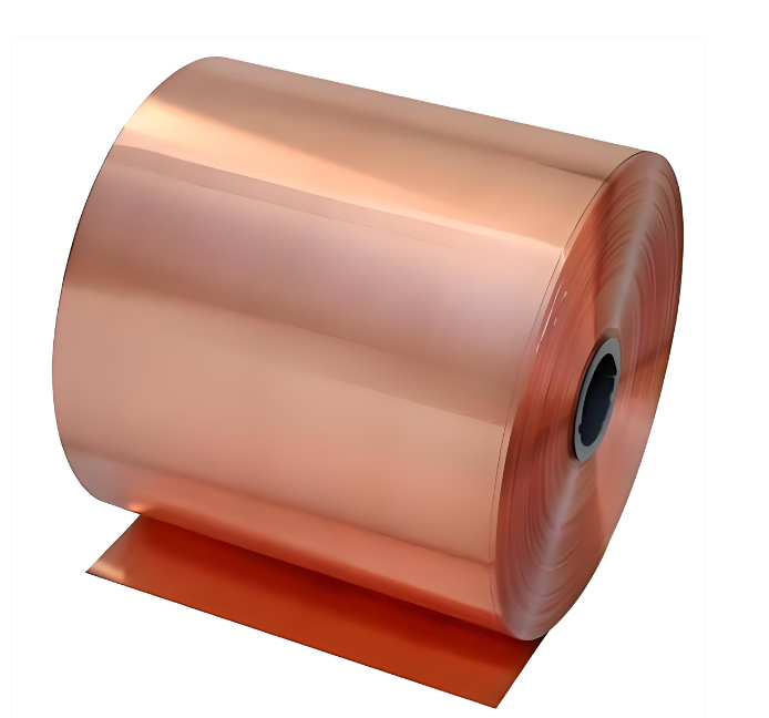
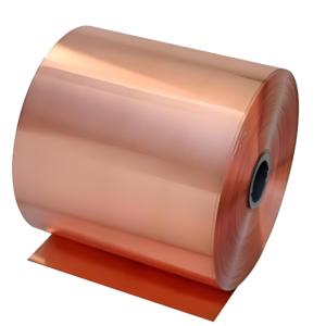
The dimensional specifications for shielding-grade copper foil differ from those used in power windings. Typical thicknesses range from 0.035mm to 0.300mm, with widths available from 6mm to 50mm . The foil is supplied in roll form, typically 100 or 200 metres per roll with a 76mm core, enabling efficient application in automated winding processes . The insulation overlay can be applied either with adhesive or through a specialised adhesive-free process that ensures excellent soldering behaviour and minimal overall thickness .
In transformer designs, copper foil shielding can also be wrapped around the outer periphery of the core to contain radiated electromagnetic emissions. A patent-protected design describes an arrangement where electromagnetic wave shielding copper foil is wound around the outer edge of the transformer core, with the foil connected through a metal gasket to a ground plane on the circuit board . This configuration effectively channels electromagnetic interference from the core to ground, significantly reducing radiated emissions and ensuring compliance with electromagnetic compatibility regulations .
Interference Suppression Components: The shielding function extends beyond transformers to related components such as toroidal cores, chokes, inverters, and signal transmission lines . Copper foil’s high flexibility enables winding around small radii, allowing for compact, high-density designs that maintain excellent shielding effectiveness .
Planar Transformers and High-Frequency Applications
The emergence of planar transformers represents a paradigm shift in transformer design, driven by the demands of modern power electronics for smaller size, higher efficiency, and better thermal performance. In planar transformers, windings are fabricated from flat copper foil embedded in multilayer printed wiring boards (PWBs), replacing traditional wound wire constructions .
Window Area Utilisation: One of the fundamental advantages of copper foil in planar transformer designs is the superior utilisation of the core window area. Foil windings provide a higher copper space factor compared to round wires or Litz wire, which require additional space for insulation between strands . This improved packing density enables more compact transformers with equivalent or better performance characteristics .
Thermal Management: Temperature control is a critical consideration in high-power-density transformers. Copper foil windings dissipate heat more effectively than traditional magnet wire due to their large surface area in contact with the surrounding insulation or cooling medium . This improved thermal dissipation capability allows for higher power densities without exceeding temperature rise limits.
Reduced Voltage Stress: The foil winding configuration facilitates a reduction in voltage stresses between turns in the winding . This characteristic is particularly advantageous in high-voltage applications where insulation reliability is paramount. The uniform electric field distribution across foil windings reduces the risk of partial discharge and extends transformer service life.
Mechanical Robustness: Foil-wound components offer increased mechanical strength compared to wire-wound counterparts . The continuous foil construction provides superior resistance to vibration and thermal cycling, making foil-wound transformers suitable for demanding environments such as aerospace, automotive, and industrial applications.
High-Frequency Loss Considerations
At elevated frequencies, transformer windings experience increased AC losses due to two principal phenomena: skin effect and proximity effect. Skin effect causes current to migrate toward the conductor surface, reducing the effective cross-sectional area and increasing resistance . Proximity effect, caused by magnetic fields from adjacent conductors, further disrupts current flow and contributes to additional losses.
Foil Height-to-Width Ratio Optimisation: Research has demonstrated that the height-to-width ratio of copper foil windings significantly influences AC losses in high-frequency transformers. In a 20 kVA/10 kHz high-frequency transformer study, the relationship between height-to-width ratio and losses was systematically analysed, leading to the establishment of appropriate constraints for loss minimisation . This optimisation approach enables designers to select foil dimensions that minimise eddy-current losses while maintaining acceptable DC resistance.
Comparison with Litz Wire: Litz wire remains superior to solid conductors, including copper foil, at frequencies above approximately 10 kHz due to its multi-strand construction that effectively divides current flow and reduces skin and proximity effects . However, copper foil offers compelling advantages in cost, thermal management, and manufacturing simplicity that make it the preferred choice for many applications below 10 kHz or where efficiency requirements are less stringent

Reviews
There are no reviews yet.