
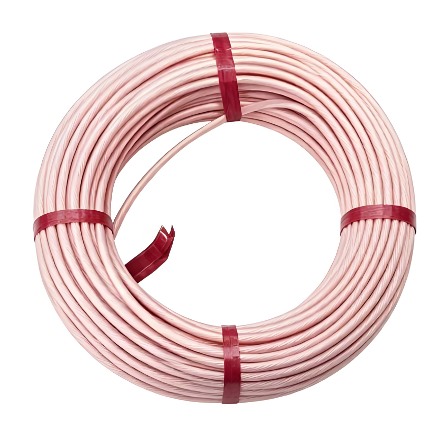
View more products about submersible pump winding wire+
1. Conductor Construction
1.1 Conductor Material
The conductor is bare copper, electrolytic grade, with conductivity suitable for continuous current-carrying service in submersible motors. The copper is oxygen-free or low-oxygen content to minimize cuprous oxide formation at grain boundaries, which under electrical stress and moisture exposure can become corrosion initiation sites. The conductor surface is cleaned immediately before insulation application to ensure adhesion between the metal and the polymer layers.
1.2 Conductor Configuration
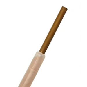
Within the 0.8–4.50 mm range, the conductor is solid (single-strand) rather than stranded. Solid construction provides dimensional stability during winding, allowing the winder to form coils that retain their geometry during insertion into stator slots. The conductor diameter spans from 0.8 mm at the lower end of the range up to 4.50 mm at the upper end.
1.3 Conductor Cross-Sectional Area
The corresponding cross-sectional areas range from approximately 0.50 mm² for a 0.8 mm conductor to approximately 15.9 mm² for a 4.50 mm conductor. This range covers the winding requirements of submersible motors from small 4-inch units up to larger 8-inch and 10-inch rewindable motors.
1.4 Conductor Diameter Tolerance
The conductor diameter is held to tight tolerances, typically within ±0.008 mm to ±0.025 mm depending on the specific diameter . This precision ensures consistent slot fill and predictable electrical resistance.
2. PE2 Insulation Layer
2.1 Material and Cross-Linking
The primary dielectric is cross-linked polyethylene, designated PE2. The polyethylene compound is free from lead and chlorine. Cross-linking is achieved through either electron beam radiation or chemical agents, creating covalent bonds between polymer chains that transform the thermoplastic polyethylene into a thermoset material . This cross-linking is the mechanism that provides the thermal stability that distinguishes PE2 from ordinary polyethylene.
2.2 Insulation Wall Thickness
The insulation wall thickness depends on the voltage rating and the conductor diameter. For wires in the 0.8–4.50 mm conductor range, the PE2 wall thickness typically ranges from 0.3 mm to 0.9 mm . Higher voltage ratings require proportionally thicker insulation.
2.3 Dielectric Breakdown Strength
The dielectric breakdown strength of the PE2 insulation is specified as at least 70 kV/mm at 20°C and 50 Hz, measured according to DIN VDE 0303-21 . This high breakdown strength provides the electrical margin necessary for reliable operation at the voltages typical of submersible motors, including operation with variable frequency drives.
2.4 Specific Insulation Resistance
The specific insulation resistance of the PE2 layer is 10¹⁶ Ω·cm at 20°C, measured according to IEC 60093 . This exceptionally high resistance value ensures minimal leakage current even under continuous immersion.
2.5 Dielectric Constant
The relative dielectric constant of the PE2 insulation is 2.3 at 20°C and 800 Hz, measured according to DIN 53483 . This low value contributes to stable electrical performance across the operating frequency range.
2.6 Operating Temperature
The PE2 insulation is rated for continuous operation at conductor temperatures up to 90°C under normal mechanical stress . In water-filled submersible motors, this permits operation in water temperatures up to 50°C without derating . At water temperatures between 51°C and 64°C, motors must be derated according to the manufacturer’s specified factors.
3. PA (Polyamide) Sheath
3.1 Material and Function
The outer layer is polyamide, commonly known as nylon. This sheath performs no primary electrical function. Its purpose is mechanical protection: it resists abrasion during winding insertion, provides a smooth low-friction surface for wire feeding, and protects the PE2 dielectric from cut-through when the wire contacts slot edges or crosses over itself in end-turn regions .
3.2 Sheath Thickness
The polyamide sheath thickness ranges from 0.1 mm to 0.3 mm, depending on the overall diameter of the PE2-insulated conductor . For wires in the 0.8–4.50 mm conductor range, the PA sheath is typically at the lower end of this range, approximately 0.1 mm to 0.2 mm.
4. Mechanical Properties
4.1 Tensile Strength
The tensile strength of the insulation is specified as at least 10 N/mm² at 23°C (±5), measured according to IEC 60811-1-1 . This value must be maintained after accelerated aging at 80°C for seven days.
4.2 Elongation at Break
The elongation at break is at least 100% at 23°C (±5), measured according to IEC 60811-1-1 . This property is also maintained after aging at 80°C for seven days, ensuring the insulation does not embrittle during service.
4.3 Flexibility and Winding Properties
The wire is designed for easy winding, with a smooth surface finish that facilitates feeding through automatic winding equipment . The PA sheath contributes to this by providing a low-friction outer surface.
5. Electrical Operating Parameters
5.1 Voltage Ratings
The PE2+PA insulation system is available in voltage ratings including 1,000 V and 3,000 V . For higher voltage applications up to 6,000 V, a semiconducting layer (HL) may be applied between the conductor and the PE2 insulation.
5.2 Test Voltage
The wire withstands a test voltage of 7,000 V DC applied for 15 minutes at 50 Hz after 48 hours of operation in water at 20°C .
5.3 Resistance Values
Conductor resistance varies with diameter. Representative values for wires in the stated range include approximately 0.0188 Ω/m for a 1.06 mm conductor, 0.0108 Ω/m for a 1.40 mm conductor, 0.00732 Ω/m for a 1.70 mm conductor, and 0.00529 Ω/m for a 2.00 mm conductor . Resistance decreases as conductor diameter increases.
6. Dimensional Specifications
6.1 Overall Diameter
The overall diameter of the finished wire—conductor plus PE2 insulation plus PA sheath—depends on the conductor size and voltage rating. For a 1.06 mm conductor, the maximum overall diameter is approximately 1.86 mm. For a 2.00 mm conductor, the maximum overall diameter is approximately 3.14 mm . The PA sheath adds a small increment to the overall diameter, typically 0.2 mm to 0.4 mm total.
6.2 Insulation Thickness Tolerance
The minimum insulation thickness is specified to ensure dielectric integrity. For conductors up to 1.0 mm, the minimum PE2 thickness is typically 0.2 mm. For conductors from 1.4 mm to 2.0 mm, the minimum thickness increases to 0.25 mm .
7. Storage and Handling
The wire should be stored in a dry environment at moderate temperature, away from direct sunlight and sources of ozone or chemical vapors. Recommended storage and processing temperatures should be observed to maintain the insulation properties before winding . The smooth PA surface should be protected from sharp objects during handling.

Reviews
There are no reviews yet.