
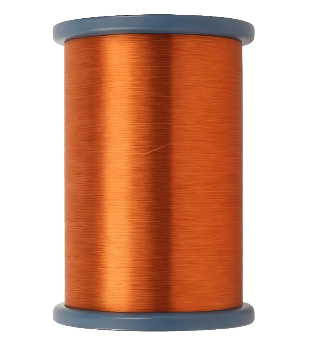
View more products about enameled copper wire+
Step 1: Pre-Repair Inspection & Fault Diagnosis
Before any disassembly, the first critical step is to identify the root cause of the motor failure, to ensure the same problem will not happen again after rewinding.
- Visual & Sensory Check: Unplug the motor completely, then inspect the housing, terminal block, and wiring for obvious burn marks, melted insulation, or oil contamination. Smell the internal components: a strong burnt paint odor usually indicates stator winding burnout, while a grease carbonization smell points to bearing failure that caused secondary winding overheating.
- Electrical Testing: Use a digital multimeter to measure the resistance of each phase winding. If the three-phase resistance deviation exceeds 5%, it confirms unbalanced winding damage. Follow this with a megohmmeter (insulation resistance tester) to check the insulation value between windings and between winding and the motor core. A reading below 0.5 MΩ for low-voltage motors means the insulation has failed completely.
- Root Cause Verification: Check the capacitor (for single-phase motors), bearing condition, cooling fan, and power supply stability. If the motor previously tripped protection frequently, ran abnormally hot, or emitted a burning smell, these hidden issues must be resolved before rewinding — otherwise, the new winding will fail again within a short period.
Step 2: Winding Wire Selection — Match Specs, Not Just Gauge
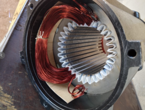
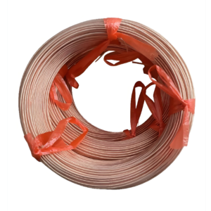
Choosing the wrong enameled copper wire is the top reason for post-repair motor performance drop or early failure. You must never replace the original wire with a random similar-looking product; every parameter must be verified carefully.
- Confirm Original Wire Specifications First: Record the original wire diameter, number of turns per slot, winding connection method, and insulation class before removing the old damaged winding. For multi-strand parallel windings (such as four thin wires merged into one winding), do not replace them with a single thick wire of the same cross-sectional area directly. Multi-strand designs offer better flexibility for slot insertion and superior heat dissipation, and a single thick wire may alter the original magnetic field distribution and reduce motor efficiency.
- Match Thermal Class to Operating Conditions: For general-purpose industrial motors that run under continuous load, 180℃ double-coated enameled copper wire is the most reliable choice. Its dual-layer insulation structure — polyurethane base coat plus polyamide outer coat — delivers a minimum temperature index of 180℃, thermal shock resistance above 200℃, and over 120 times of abrasion resistance, making it far more durable than standard 130℃ or 155℃ wires. For high-temperature, high-humidity, or chemical-corrosion working environments, you can upgrade to 200℃ or 220℃ grade enameled wire for extended service life.
- Avoid Improper Gauge Substitution: If you have to make a temporary substitution (for example, replacing a 0.95mm wire with a 0.90mm one), you must calculate the parameter deviation first. A 0.90mm wire has roughly 10% higher resistance than a 0.95mm wire, which will increase motor heat generation and reduce current-carrying capacity. You can compensate by adding a reasonable number of extra turns, but you must verify that the adjusted winding can still fit in the original stator slot, and confirm that the final three-phase resistance deviation is controlled within 2%.
- Prioritize Certified Quality: Always select enameled copper wire made from 99.97% oxygen-free copper, with strictly tested insulation thickness, breakdown voltage, and elongation. Low-quality recycled copper wire with thin, uneven insulation will cause unexpected turn-to-turn short circuits, leading to motor burnout shortly after the repair.
Step 3: Standardized Rewinding & Post-Repair Testing Process
Even with the best winding wire, careless operation during rewinding will ruin the repair quality. Follow this full workflow to ensure the restored motor matches or even exceeds its original performance:
- Remove Old Winding & Clean the Stator: Extract all the damaged old windings, then clean the stator core slots thoroughly with a soft brush and compressed air. Do not use sharp metal tools that will scratch the core surface, as this will increase iron loss and reduce motor operating efficiency. If the stator core shows signs of overheating deformation, you must perform core loss testing before proceeding.
- Slot Insulation Preparation: Insert high-temperature insulating paper into every stator slot, making sure it fully covers the slot inner wall to prevent the enameled wire from directly touching the metal core and causing ground faults. Add phase insulation between different phase windings to avoid inter-phase breakdown.
- Winding & Insertion: Wind the new enameled copper wire strictly according to the original recorded number of turns and wire gauge. Handle the wire gently during slot insertion to avoid scratching the insulation layer with sharp slot edges. Arrange the wires neatly inside the slot, and do not leave any strands squeezed outside the slot opening.
- Lacing & Connection: After all windings are inserted, lash the end turns tightly with high-temperature lacing cord to prevent them from shifting under the strong electromagnetic force during high-speed motor operation. Connect the winding leads according to the original wiring diagram, and mark each phase clearly for later testing.
- Pre-Impregnation Testing: Before applying insulation varnish, test the three-phase resistance balance and insulation resistance again to catch any wiring errors or insulation damage at this stage. If you find any unqualified readings, correct them before moving forward — it will be almost impossible to fix after varnish impregnation.
- Varnish Impregnation & Curing: Use vacuum-pressure impregnation to fully saturate the entire winding with high-temperature insulation varnish. This step locks all the wires in place, improves overall insulation strength, and greatly enhances the winding’s heat dissipation performance. Cure the winding in a temperature-controlled oven following the varnish manufacturer’s recommended time and temperature, to ensure full curing without overheating the insulation.
- Final Assembly & Commissioning: Reassemble the motor, install new high-temperature grease lubricated bearings, then perform no-load test run for at least 1 hour. Monitor the no-load current, vibration level, and running temperature in real time. After confirming no abnormal noise, overheating, or current imbalance, you can put the repaired motor back into service.

Reviews
There are no reviews yet.