
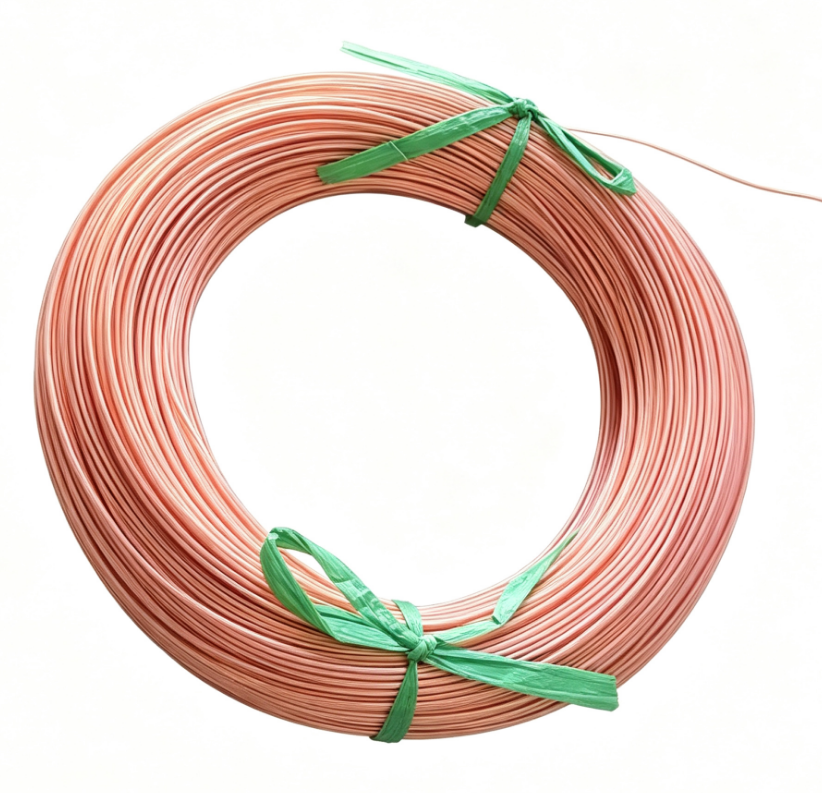
View more products about submersible pump winding wire+
The Manufacturing Process
Conductor Preparation
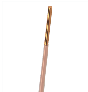
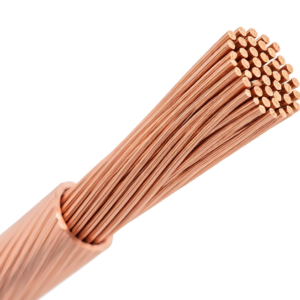
The process begins with a bare copper conductor, either solid or stranded depending on the cross-sectional area and flexibility requirements of the intended motor . Solid conductors dominate the smaller size range, from approximately 0.6 mm to 4.6 mm diameter, while stranded constructions are employed above roughly 3.5 mm where the wire must withstand repeated bending during winding insertion . The copper is drawn to the specified diameter and cleaned to remove drawing lubricants, oxide films, and any particulate contamination. Surface cleanliness is critical because the subsequent polymer layers are applied by extrusion directly onto the metal, and any residue will impair adhesion.
For high-voltage applications, typically at operating voltages of 3 kV and above, a semiconducting layer may be applied between the copper and the primary insulation . This layer equalizes the electric field at the conductor surface, preventing localized stress concentrations that could initiate dielectric failure. The semiconducting compound is applied by a separate extrusion step or co-extruded with the insulation depending on the production line configuration.
Cross-Linked Polyethylene Application
The prepared conductor passes through a crosshead extrusion die, where molten polyethylene is pressed around the moving wire . The polyethylene used for PE2 insulation is a specially formulated compound, free from lead and chlorine, that has been designed for subsequent cross-linking . The extrusion temperature is carefully controlled to ensure complete melting and uniform flow without thermal degradation of the polymer. The die geometry determines the insulation wall thickness, which typically ranges from 0.3 mm to 3.5 mm depending on the voltage rating of the finished wire .
Immediately after exiting the die, the coated conductor enters a cooling trough where water is applied uniformly around the circumference . Uniform cooling is essential to prevent differential shrinkage that could introduce eccentricity or internal stresses in the insulation. The cooled wire then passes through on-line gauges that measure diameter, wall thickness eccentricity, and detect pinholes or spark faults in the coating .
The defining characteristic of PE2 insulation is the cross-linking step. Cross-linking transforms the thermoplastic polyethylene into a thermoset material by creating covalent bonds between adjacent polymer chains. This is typically achieved through one of two methods: chemical cross-linking, where a peroxide or silane agent is compounded into the polyethylene before extrusion and later activated by heat or moisture, or physical cross-linking, where the extruded insulation is exposed to high-energy electron beam radiation . The radiation method produces the designation “PE2” in some manufacturers’ nomenclature, indicating physical rather than chemical cross-linking . Regardless of method, the result is a material with markedly improved thermal stability, allowing continuous operation at conductor temperatures that would cause thermoplastic polyethylene to soften and deform.
Polyamide Sheathing
After the cross-linked polyethylene layer has been applied and cured, the wire passes through a second extrusion operation where a thin polyamide sheath is applied . The polyamide, typically a nylon compound selected for its combination of toughness, low friction, and thermal stability, forms the outermost layer of the finished wire. The sheath thickness is considerably less than the PE2 layer, generally between 0.1 mm and 0.3 mm . The polyamide is extruded at temperatures above its melting point but well below its decomposition threshold; for the polyamide grades used in winding wire applications, melting points in the range of 310°C to 370°C are typical, with processing windows that require careful temperature control to avoid degradation .
The polyamide sheath serves purely mechanical functions. It protects the underlying PE2 dielectric from abrasion during handling and winding insertion, provides a smooth low-friction surface that facilitates wire feeding through automatic winding equipment, and resists cut-through when the wire is pressed against slot edges or crossed over itself in the end-turn region . The sheath also contributes to the wire’s resistance to water and oil ingress, though the primary barrier function is performed by the cross-linked polyethylene.
Final Testing and Spooling
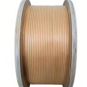
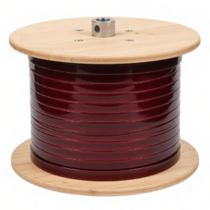
Completed PA/PE2 wire undergoes rigorous quality testing before packaging. High-voltage routine testing is performed with the wire immersed in water, applying alternating current at 50 Hz for a specified duration to verify insulation integrity under conditions simulating actual service . Dimensional checks confirm conductor diameter, insulation wall thickness, overall diameter, and concentricity. Mechanical tests may include tensile strength and elongation measurements on both the insulation and the finished wire, as well as adhesion testing between the polymer layers and the copper . The wire is then spooled onto reels under controlled tension, with the spool size selected according to the wire diameter and the quantity required for typical motor rewinding jobs.
Materials Required for Submersible Motor Rewinding
Rewinding a submersible motor with PA/PE2 wire involves more than simply replacing the copper. The process requires a specific inventory of materials that address the electrical, mechanical, and sealing requirements unique to wet-stator designs. Preparation should begin well before the motor is disassembled.
The Winding Wire Itself
The primary material is, of course, the PA/PE2 winding wire in the correct size. Selection of wire diameter is governed by the motor’s original design specifications: the number of turns per coil, the slot dimensions, and the desired electrical characteristics. Manufacturer winding data tables specify wire diameters for particular motor ratings, often listing two dimensions that correspond to the conductor diameter and the overall diameter with insulation . If the motor is being upgraded from PVC to PA/PE2 insulation, the larger overall diameter of the PA/PE2 wire must be accounted for in the slot fill calculation. Insufficient slot fill can make winding insertion impossible, while excessive fill may damage the insulation during assembly. A sufficient quantity of wire must be procured to allow for waste, lead extensions, and potential rework.
Slot Insulation Materials
Before the winding wire is inserted, the stator slots must be lined with ground insulation that separates the copper from the ferrous core. For submersible motors, this insulation must maintain its dielectric properties under continuous immersion. Materials such as polyester film, polyimide film, or composite laminates combining a polyester backing with a fibrous surface are commonly employed . The liner is cut or folded into a cuff shape that extends beyond the slot edges at both ends, protecting the wire from the sharp corners of the laminations during insertion and providing adequate creepage distance between the winding and ground. The thickness of the slot liner is selected according to the motor’s voltage rating and the available slot space.
Phase Insulation and Separators
Where different phases of the winding occupy the same slot, phase insulation must be placed between the coil groups. This insulation, often made from the same film materials as the slot liners or from a flexible composite with higher dielectric strength, prevents phase-to-phase short circuits that could result from insulation damage during operation . Slot separators or wedges may also be required at the slot opening to retain the winding and prevent movement under electromagnetic forces. These components must be compatible with the motor’s internal fluid, whether clean water or a water-glycol mixture.
Sealing Components
Submersible motors are sealed against the surrounding water by a combination of O-rings, gaskets, and cable entry seals. These components are generally not reusable after disassembly and must be replaced. O-rings sized for the motor housing joints, bearing housings, and terminal plate must be procured in the correct material, typically nitrile or fluoroelastomer compounds resistant to water and temperature cycling. Gaskets for the terminal plate and flange connections must be matched to the motor design. The cable seal assembly, which prevents water from entering the motor along the power cable, is a critical component that should be replaced rather than reused. Heat-shrinkable tubing with adhesive lining may be required for terminating the motor leads to the cable .
Fasteners and Hardware
While not consumed in the same way as insulation materials, various fasteners may require replacement due to corrosion, thread damage, or loss during disassembly. Terminal studs and nuts, bearing retaining rings, thrust bearing components, and drain plugs should be inspected and replacements obtained as needed. Thread compounds or anti-seize lubricants suitable for submerged service should be on hand for assembly.
The Motor’s Internal Fluid
Water-filled submersible motors require a specific filling fluid before final assembly. In some designs, clean potable water is acceptable; in others, a water-glycol mixture or a proprietary fluid specified by the manufacturer must be used. The correct fluid must be procured in sufficient quantity to fill the motor completely, accounting for the displacement of the internal components. Using an incorrect or contaminated fluid can cause corrosion, lubrication failure, or electrical problems shortly after the motor is returned to service.

Reviews
There are no reviews yet.