
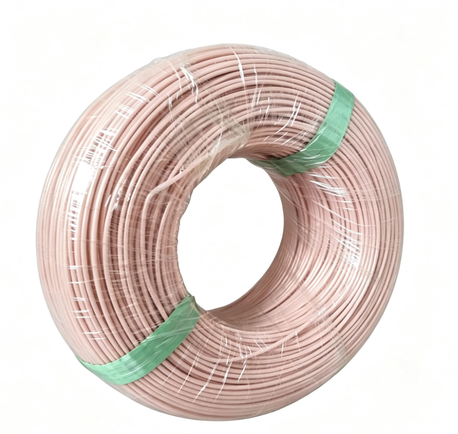
View more products about submersible pump winding wire+
Material Composition of PE2+PA Winding Wire
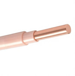
The PE2+PA winding wire is constructed as a layered insulation system applied over a bare copper conductor. The designation “PE2” refers to cross-linked polyethylene, while “PA” denotes polyamide, commonly known as nylon. Each layer serves a distinct and complementary function, and the combination produces a wire capable of surviving years of submerged operation.
Copper Conductor
The conductor itself is either a solid or stranded bare copper wire. Solid conductors are typically used in smaller diameters, ranging from approximately 0.6 mm to 4.6 mm, while stranded constructions are employed for larger cross-sections where flexibility during winding becomes necessary . The copper must be oxygen-free or electrolytic-grade to ensure consistent resistivity and to minimize the risk of corrosion-related failure. The conductor diameter and strand configuration determine the current-carrying capacity of the finished winding.
PE2 Insulation Layer
The primary electrical insulation is cross-linked polyethylene, applied directly over the copper conductor. The “PE2” designation indicates that the polyethylene has undergone cross-linking, a process that creates covalent bonds between polymer chains and transforms the thermoplastic into a thermoset material with markedly improved thermal stability . This cross-linking is what allows PE2-insulated wires to operate at significantly higher temperatures than ordinary PVC-insulated wires. While standard PVC submersible wires are limited to approximately 30°C water temperature without derating, PE2-based wires can operate in water up to 50°C in typical submersible motor designs, with some configurations permitting even higher temperatures under controlled conditions . The cross-linked polyethylene provides high dielectric strength, with typical breakdown values around 70 kV/mm, and maintains excellent insulation resistance even after prolonged immersion .
PA (Polyamide) Outer Sheath
Applied over the PE2 insulation is a thin outer sheath of polyamide, typically with a wall thickness between 0.1 mm and 0.3 mm . The polyamide layer does not serve as primary electrical insulation. Instead, its purpose is mechanical protection. During the winding process, the wire passes through slot liners, bends around end turns, and is subjected to abrasion against stator laminations. The polyamide sheath provides a tough, smooth surface that resists scuffing and cut-through, protecting the critical PE2 dielectric layer from mechanical damage . Additionally, the polyamide outer layer contributes to the wire’s resistance to water and oil ingress and helps maintain insulation integrity under thermal cycling.
Semiconducting Layer for High-Voltage Applications
For applications at voltages of 3 kV and above, manufacturers may incorporate a thin semiconducting layer between the copper conductor and the PE2 insulation . This layer serves to equalize the electric field across the conductor surface, preventing localized stress concentrations that could lead to premature dielectric failure. While most submersible pump motors operate at lower voltages, this refinement illustrates the adaptability of the PE2+PA system to higher-power applications.
Suitability for Rewinding Different Submersible Pump Motors
PE2+PA winding wire is used as standard insulation in rewindable submersible motors from numerous manufacturers, including Vansan, Panelli, Franklin Electric, Ebara, DAB, and Grundfos . The rewindable construction is fundamental to the economics of submersible pump ownership: when a motor winding fails due to insulation breakdown, moisture ingress, or electrical fault, the motor can be stripped and rewound rather than replaced entirely .
The PE2+PA system is particularly well-suited for rewinding motors that operate under conditions exceeding the capabilities of standard PVC insulation. Motors that have failed prematurely because their original PVC windings could not tolerate water temperatures above 30°C can often be upgraded to PE2+PA windings during the rewind process, thereby increasing the motor’s thermal margin and potentially extending its service life . This upgrade path is commonly applied to 4-inch, 6-inch, 8-inch, 10-inch, and 12-inch submersible motors from various manufacturers .
The wire is compatible with both water-filled and oil-filled motor designs, though the vast majority of PE2+PA applications are in water-filled motors where the winding is in direct contact with the cooling fluid. The insulation system is also suitable for motors controlled by variable frequency drives (VFDs), where the winding must withstand the additional electrical stresses imposed by pulse-width modulation waveforms .
Preparation Process for Rewinding Submersible Motors
Rewinding a submersible motor with PE2+PA wire requires a systematic preparation process. Unlike dry motor rewinding, where the primary concerns are electrical and thermal, submersible motor rewinding must address the additional challenges of water tightness, corrosion protection, and the mechanical integrity of the insulation system under continuous immersion. The following steps outline the essential preparation procedures.
Safety Isolation and Documentation
Before any work begins, the motor must be electrically isolated from all power sources. Lockout/tagout procedures should be applied to the control panel or disconnect switch. The motor’s nameplate data—voltage, horsepower, phase, frequency, service factor, and serial number—should be recorded for reference during rewinding. Any available history of the motor’s operation and failure mode should be reviewed to inform decisions about potential upgrades, such as using a higher insulation class or adjusting the winding configuration.
Motor Extraction and External Inspection
The submersible pump and motor assembly must be pulled from the well or water source. This requires appropriate lifting equipment, as submersible pump assemblies can be heavy and are often located at significant depth. Once at the surface, the motor should be cleaned externally to remove mud, scale, and biological growth. The external condition of the motor housing, cable connections, and seals should be documented, as this information helps diagnose the cause of failure and identifies any components requiring replacement beyond the winding itself.
Disassembly and Component Removal
The motor is disassembled to expose the stator assembly. For water-filled motors, this involves draining the internal fluid and removing the top and bottom bearing housings, thrust bearing assemblies, and rotor. The stator—the stationary component containing the winding slots—is the focus of the rewinding process. All associated components, including the cable and cable seal assembly, mechanical seal, bearings, and O-rings, should be inspected for wear and replaced as needed. The stator core itself must be examined for evidence of overheating, core damage, or lamination shorting that could affect the rewinding.
Stator Cleaning and Insulation Removal
The old winding must be removed from the stator slots. This is typically accomplished by heating the stator to soften the varnish or potting compound, then mechanically extracting the copper. For water-filled motors, the winding may be held in place by the slot liner system and the absence of heavy varnish, but removal still requires care to avoid damaging the stator laminations. After the copper is removed, the stator slots must be thoroughly cleaned of all insulation residue, varnish, and contaminants. Slot files or brushes are used to remove debris without cutting into the lamination steel. The slot dimensions and core length are measured to confirm the wire size and winding data.
Slot Insulation and Liner Installation
New slot liners are installed to provide the ground insulation between the winding and the stator core. The liner material must be compatible with the motor’s internal environment—typically a water-resistant film or paper that maintains dielectric integrity under immersion. The liner is sized to extend beyond the slot edges at both ends, protecting the wire during insertion and providing adequate creepage distance. For PE2+PA wire, the slot liner must accommodate the larger outer diameter of the insulated wire compared to standard enameled wire, which may require adjusting the slot fill or reducing the number of turns if the original design used thinner insulation.
Wire Selection and Winding Data Verification
The correct PE2+PA wire size must be selected based on the motor’s original design specifications and the desired performance. The wire is typically specified by conductor diameter, with standard sizes ranging from approximately 0.8 mm to 3.4 mm for submersible motor applications . If the original motor used PVC insulation and the rewind is intended to upgrade to PE2+PA, the wire size must be adjusted to account for the different insulation wall thickness. The winding data—number of turns per coil, coil pitch, parallel paths, and connection scheme—must be verified against manufacturer specifications or calculated from the motor’s electrical characteristics. Because submersible motors are often designed with specific slot fills and cooling considerations, deviations from the original winding data should be minimized unless an intentional performance modification is desired.
Winding Insertion and Connection
The PE2+PA wire is wound into the prepared stator using manual or semi-automatic winding equipment. The wire’s polyamide outer sheath provides a smooth surface that facilitates insertion, but care must be taken to avoid sharp bends or abrasion against slot edges. The winding is typically inserted as pre-formed coils or as random-wound turns, depending on the motor design. Once all coils are in place, the end turns are shaped and secured. The phase connections are made according to the motor’s designed connection scheme (star or delta), and the winding resistance and insulation resistance are measured to verify correctness before further processing.
Final Testing and Assembly
Before the rotor is installed, the stator winding should undergo insulation resistance testing, surge comparison testing between phases, and a high-potential test at the appropriate voltage for the motor’s rating. Any discrepancies must be corrected before proceeding. The rotor, bearings, thrust bearing, seals, and housings are then reassembled with new O-rings and gaskets. The motor is filled with the specified fluid—clean water or a water-glycol mixture for water-filled motors—and sealed. After assembly, the motor should be megger-tested to confirm insulation integrity and, where possible, run-tested before being returned to service.

Reviews
There are no reviews yet.